9+ tin lead phase diagram
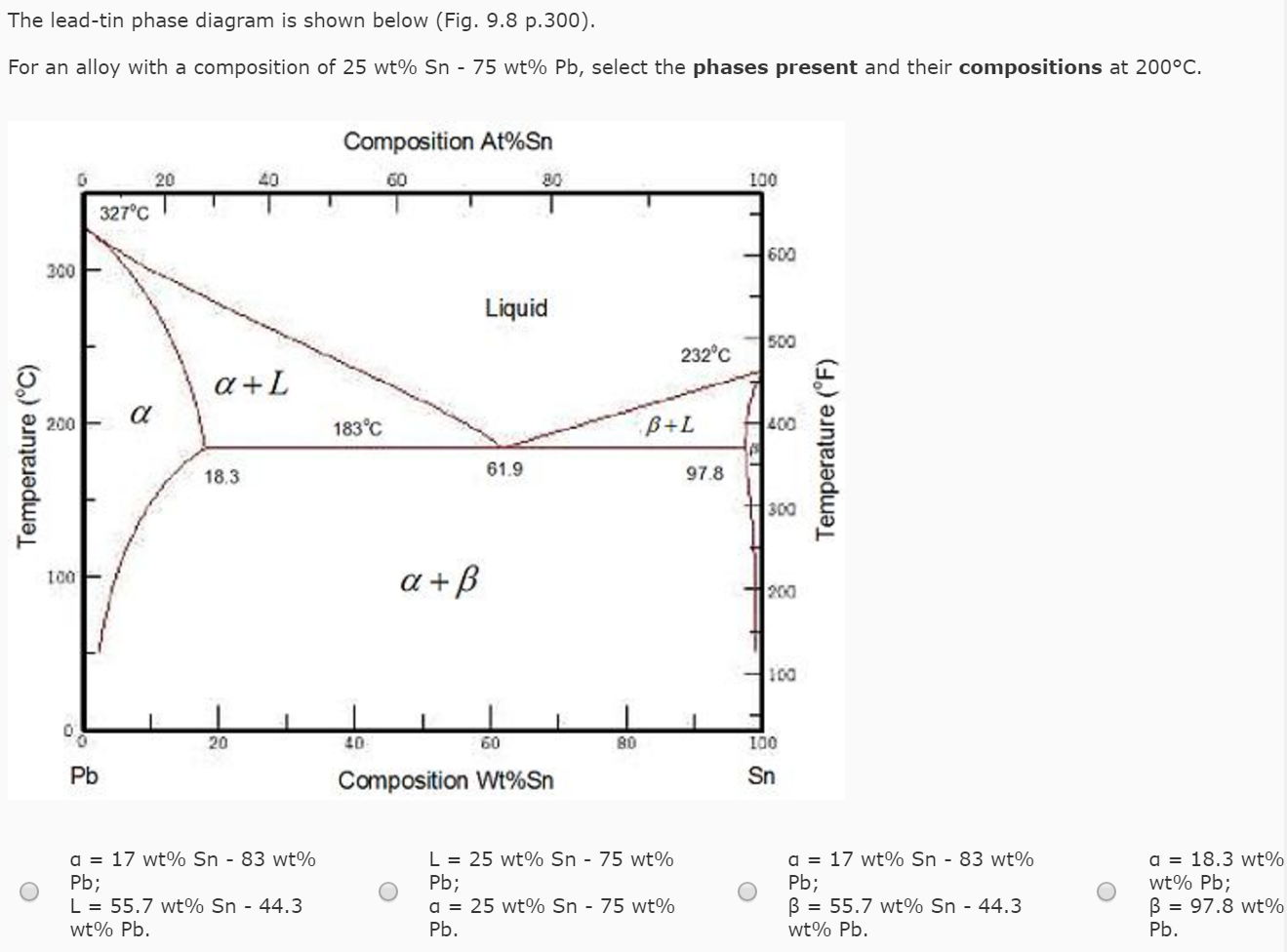
93FE From the lead-tin phase diagram Figure 98 e which of the following phasesphase combinations is present for an alloy of. Remove the outer steam jacket in front of the cradle and insert the specimen rod.

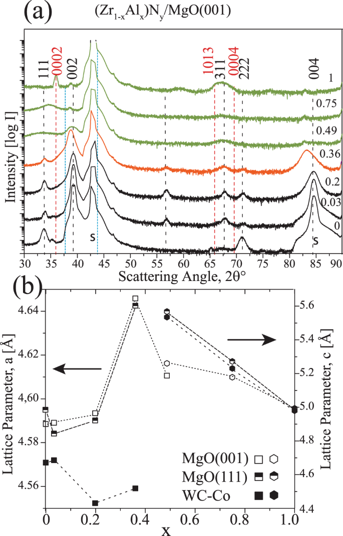
Self Structuring In Zr1 Xalxn Films As A Function Of Composition And Growth Temperature Scientific Reports
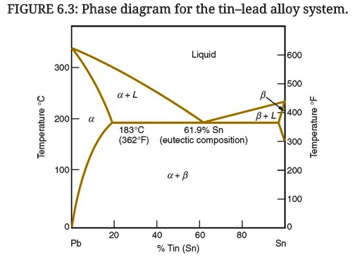
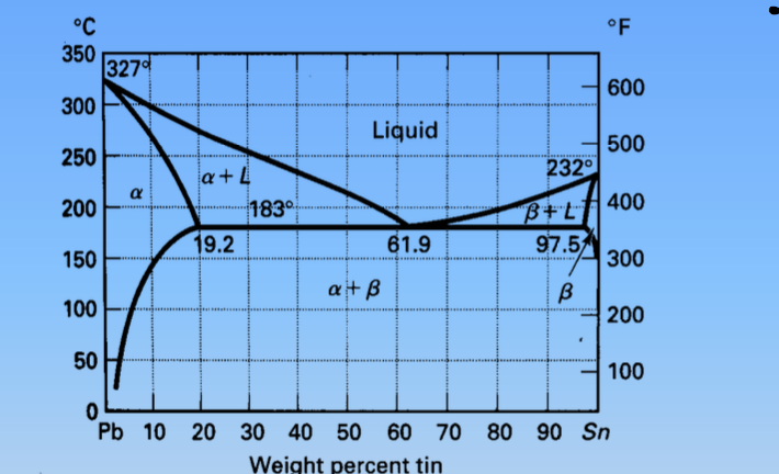
Figure 1 shows the Pb-Sn phase diagram and the composition for present experiments in which it is very clear that the eutectic temperature is 183 C and the liquid-solid transition.

. Indicates key paper. The lead-tin phase diagram was mad using the information on the table the maximum solid solubility points for lead in tin and tin in lead and the melting points for pure lead and pure tin. FigMre 99 The lead-tin phase diagramFor a 40 wt Sn-60 wt.
Modimechanicalengineeringtutorials mechanicalmagicmechanicallearningtutorialsWelcome to My YouTube Channel MODI MECHANICAL ENGINEERING TUTORIALSThis ch. LEAD-TIN PHASE EQUILIBIRUM - Free download as Word Doc doc PDF File pdf Text File txt or read online for free. C Compared with the alloy with 619 Tin which.
Computing fraction of liquid in a two-phase region. Chemical Engineering questions and answers. Chang A Thermodynamic Analysis of the PbSn System and the Calculation of the PbSn Phase Diagram Calphad 5 267276.
Video created by Université de Californie à Davis for the course Materials Science. Another great example is the lead-tin phase diagram. The eutectic point is the exact temperature and composition at which the liquid.
That corresponds to a set of. In lesson nine well deal with how to make. Video created by University of California Davis for the course Materials Science.
10 Things Every Engineer Should Know. Thats the mixture from the first cooling curve plotted above. The lead-tin Pb-Sn phase diagram with three different solder compositions marked out.
Welcome to week 5. Welcome to week 5. Procedure Select a specimen bar and measure its length L1.
10 Things Every Engineer Should Know. Suppose you have a mixture of 67 lead and 33 tin. From Figure 9 a horizontal tie line can be constructed across the L phase region at about 800 C which intersects the L L phase boundary at 76 wt Ag and also the L phase.
The purpose of this lab was to study lead-tin phase equilibrium. One that those of you who have been involved in maybe bench top electronics would be familiar with as the basis of a lot of the. Note room temperature T1.
In lesson nine well deal with how to make things. Based on the following Tin-Lead phase diagram for the alloy with 30 Tin and 70 Lead a Approximately what is Tin. Figure 84 a The binary lead-tin phase diagram Ce is the eutectic composition b The microstmcture of an alloy of.
Suppose it is at a temperature of 300C. The eutectic line is a horizontal line drawn between two one-phase fields a the eutectic temperature. One eutectic and two non-eutectic Plumbers solder and a high melting point solder.

Solved Using The Lead Tin Phase Diagram In Figure 6 3 Chegg Com

Materials Science Tutorials

Development Of The Chemistry Of Indium In Formal Oxidation States Lower Than 3 Chemical Reviews

Phase Diagrams Tin And Lead Part 3 Of 3 Youtube

The Lead Tin Pb Sn Phase Diagram With Three Different Solder Download Scientific Diagram
Phase Diagrams Dt Online

The Lead Tin Pb Sn Phase Diagram With Three Different Solder Download Scientific Diagram

Solved The Lead Tin Phase Diagram Is Shown Below Fig 9 8 Chegg Com

Polyoxometalates Functionalized Electrodes For Photo Electrocatalytic Applications Recent Advances And Prospects Acs Catalysis

Tuning Phase Transition And Thermochromic Properties Of Vanadium Dioxide Thin Films Via Cobalt Doping Acs Applied Materials Interfaces

19 The Lead Tin Phase Diagram Used In Computations For Relative Amounts Download Scientific Diagram

Phase Diagrams Tin And Lead Part 1 Of 3 Youtube

Solved Please Refer To The Phase Diagram For Lead Tin On Chegg Com

Binary Phase Diagram For A Lead Tin Alloy B Nacl Nano3 Mixture Download Scientific Diagram

Binary Phase Diagram For A Lead Tin Alloy B Nacl Nano3 Mixture Download Scientific Diagram

Multicomponent Tixnbcral Nitride Films Deposited By Dc And High Power Impulse Magnetron Sputtering Sciencedirect

Solved C 350 327 600 300 Liquid 250 500 2320 A A 1 200 Chegg Com